Patching: an overview
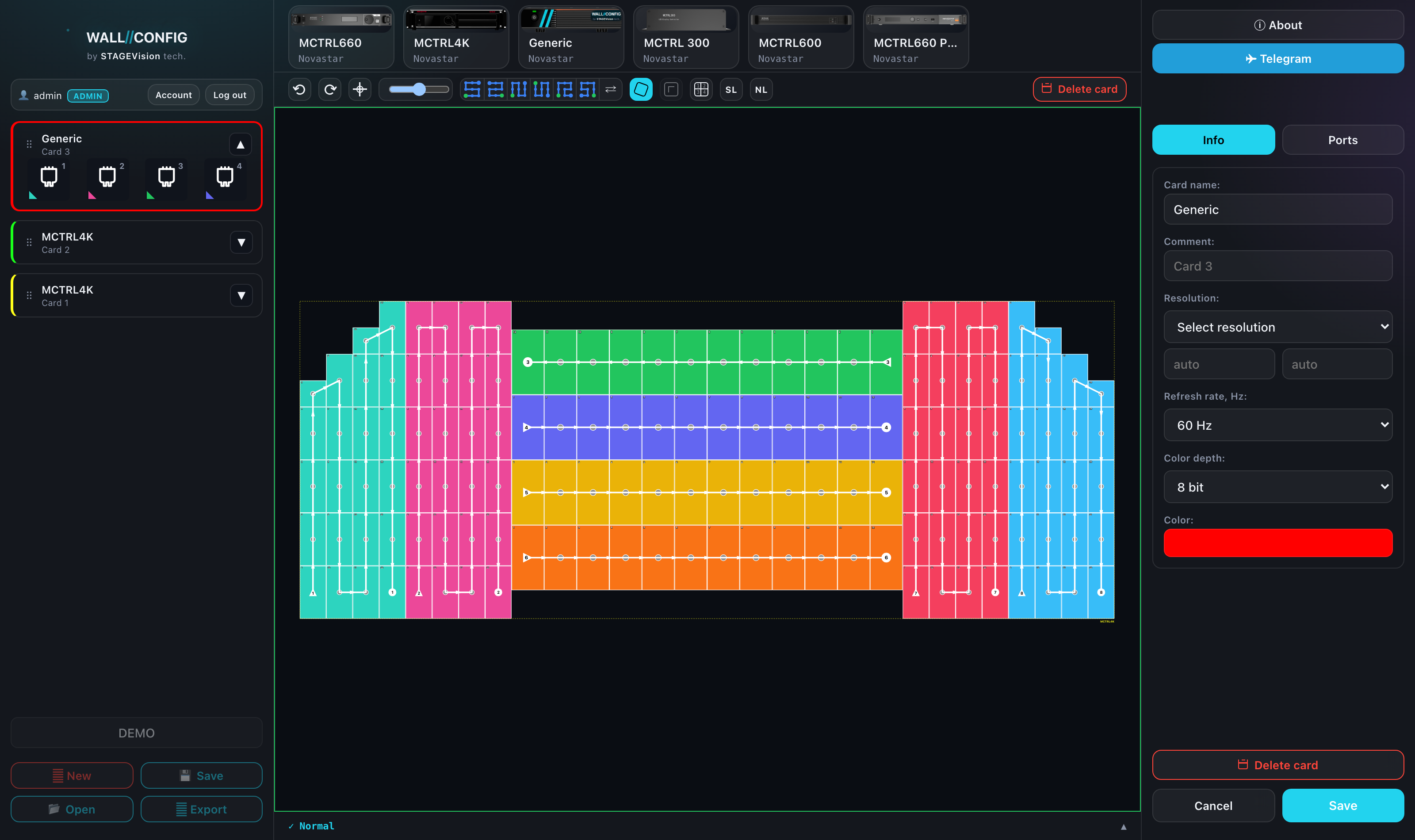
Patching turns a finished layout into a wiring plan: cabinets are distributed across the Ethernet ports of processing cards, producing the plan an installer runs cable by. The mode answers the one question that matters on site — which cabinet is connected to which port of which card, and in what order the chain runs.
What this mode does
In the ordinary editor you build the geometry of the wall. Patching adds the data-transmission logic on top of it: every port pulls a chain of cabinets, and every port has a ceiling on the number of pixels it can carry.
Patching never changes the screen layout itself — it works on top of it. The cabinets stay where they are; you only assign them ports and an order in the chain.
Entering and leaving
- Build the layout in the ordinary editor — patching works on screens that are already placed.
- Click Patch in the right-hand group of the toolbar. The left panel switches to the list of processing cards.
- Patch the wall (see below).
- Save writes the scheme into the project and closes the mode. Cancel rolls back every change made in this session.
"Cancel" here is a full rollback of the whole session, not a single Ctrl + Z step. A snapshot is taken when you enter the mode, and leaving via "Cancel" returns you to exactly that.
Two layouts: data and power
The mode holds two independent layouts of one project. By default you lay out the data — the chains of card ports. The Power button on the right-hand side of the toolbar switches to the power layout: the same cabinets grouped into PowerCon lines, with their own norms and their own styling. In full: Power patching.
Neither affects the other: a cabinet assigned to a card port has nothing to do with the power line it is plugged into. Signal and electricity run different routes.
Exporting the scheme
A finished patch goes into processor files — SmartLTC and NovaLCT — into a Patch IMG picture for the installers, and into a public link: the crew opens it without an account and without edit access.
Short checklist
- Build the wall layout.
- Enter "Patch" and add the processing cards.
- Pick a port → click cabinets in loom order, or drag a marquee with a traversal pattern.
- Watch that no port is overloaded.
- Turn on Mapper and check the numbering.
- Remove any card overlaps.
- If you need it, switch to Power and lay out the power lines.
- "Save" → export a file or send a link.
Next
- Processing cards — where the ports come from.
- Assigning cabinets — by hand, one at a time.
- The automatic marquee — fast, with a traversal pattern.
- Load, Mapper and the check — what to verify before saving.
- Power patching — PowerCon lines and overload control.
- Port load and card technologies — where the limits come from.